Drawing standard UML diagrams
Introduction
Unified Modeling Language (UML) is a standard pictorial language for specifying, visualizing, contructing, and documenting the artifacts of software systems. This articles answers common questions like what was the need of UML, what are the different kind of models, and how to draw and interpret these models.
History
Multiple modellling techniques without a common standard led to confusing documents of software systems. Hence, one group called Object Management Group (OMG) proposed a draft of UML 1.0 spec in 1997.
Communication
Different roles like Product Owner, Business Analyst, Architect, Operations, Quality Assurance, Developer. All need to communicate clearly and make sure everyone understands the same meaning. Terms use by business people and by technical people are bit different.
Hence, there was a need of common Language of communication Moreover, people are working remotely and we need to make sure that those who are not in the meeting are also communicated exactly same thing.
Tools
Informal tools like whiteboard and camera or some formal tools that can generate the required figures. I use draw.io to quickly create basic diagrams.
Basics
- Types of models (Structural and Behavioral)
- Basic Building Blocks
- Key Considerations to keep in mind
Structural Modelling
It represents the physical component of the system. What those components consists of and where are they placed. So, it's like a blueprint of the system. Thus, it shows the conceptual view of the system consisting of static parts.
Examples include Class diagram, Component diagram, and Deployment diagram.
Behavioral Modeling
It represents the interaction between the structural diagrams. Thus it deals with the functionality of the system. It shows how the process occurs in real time system which consists of dynamic parts.
Examples include Use Case diagram, Sequence diagram, State diagram, and Activity diagram.
Basic Building Blocks
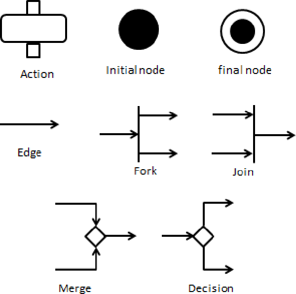
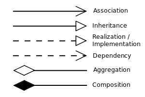
Basic building blocks required are Things (class, component, node, actor), Activities (messages, states, actions) and Relationships (association, inheritence, dependency etc.) Here are some figures to explain these symbols and relationships.
Key Considerations to keep in mind
- Keep diagram clean
- Readable Number of lines crossing each other should be minimum.
- Focused What is needed must be there and nothing extra.
- Precise Make sure everyone understand the same meaning.
- Goals
- Visualize
- Specify
- Document
- Keep the target audience in mind and try to put yourself in their shoes.
Now let's deep dive into each different type of Structural and Behavioral models
Structural Modelling
- Class Diagram
- Component Diagram
- Deployment Diagram
Class Diagram
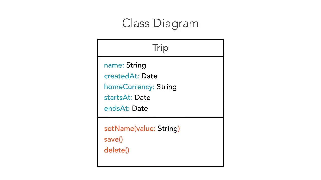
Identifies the vocabulary and relationships. It's commonly used in Object Oriented Programming, where the class diagram shows the name of class, it's attributes and their data types, and the methods of that class.
Eg: Trip class diagram.
Component Diagram
Model the physical aspects of the system. Visualize how the components are organized in a system. It does not describes the functionality, just the components used to make those functionalities. Hence, here we identify the interfaces and define replaceable parts.
Eg: Modelling a database schema.
Deployment Diagrams
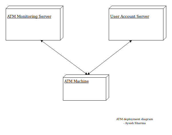
Map components to physical systems. Visualize hardware and network dependencies of a system, where those components are deployed. Represented using nodes which are physical hardware used to deploy the app. Big picture of how the system is functioning.
Eg: Visualize the hardware topology of a system.
ATM Deployment diagram example
Behavioral Modelling
How the components interact with each other. What our system does and how. Interaction is basically a message exchange between two UML components.
- Use Case Diagrams
- Sequence Diagram
- State Diagram
- Activity Diagram
Use Case Diagram
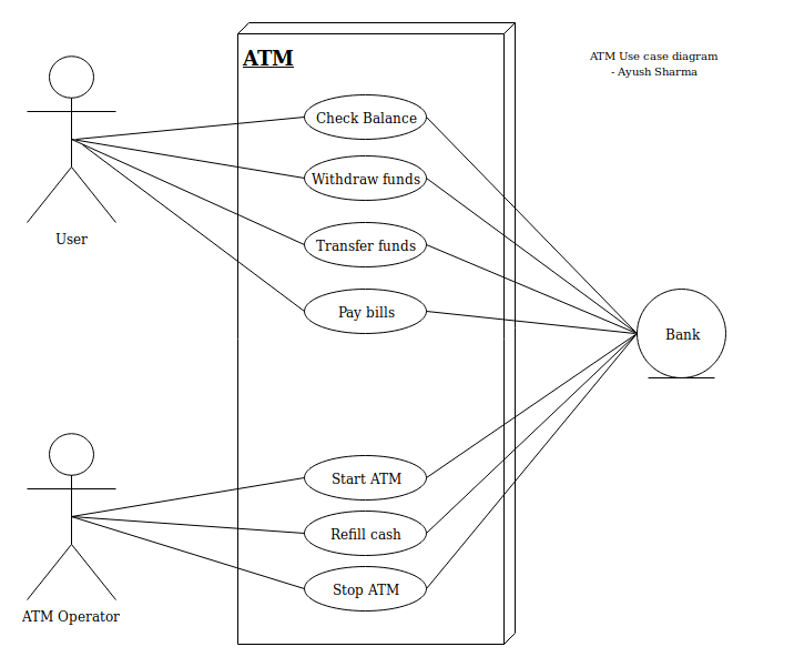
Represents a particular functionality of a system using actors, and their relationships. They convey details about what is happening but doesn't say anything about how it is happening.
Eg: Requirement analysis of a user story or visualization of System Interations.
ATM Use Case diagram example
Sequence Diagrams
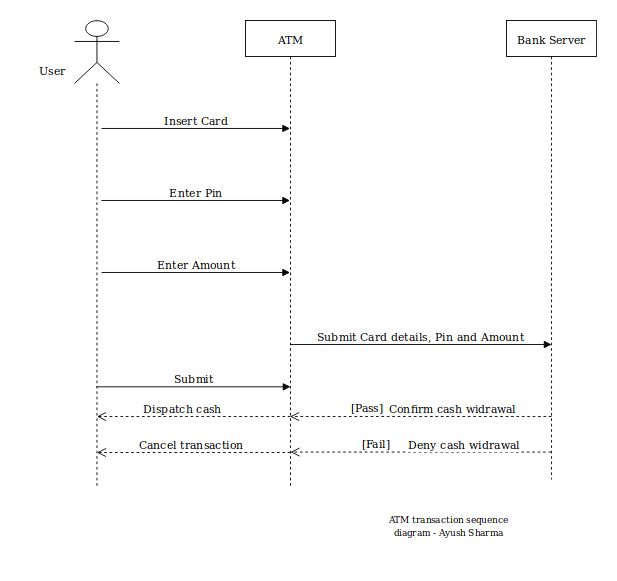
Visualize the sequence of message flow in a system to perform a specific functionality. It represents the dynamic aspect of the system. It's like a snapshot of the running system at a particular moment.
Eg: sequentially ordered messages between objects.
ATM transaction sequence diagram example
State Diagram
Real-time system is expected to be reacted by some kind of internal/external events.
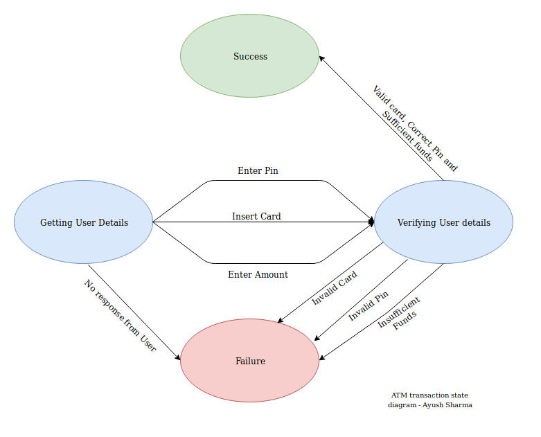
State diagrams represents the event driven state change of a system during it's lifetime.
Eg: Modelling states of an object in a system and the events causing this state transitions.
ATM transaction state diagram example
Activity Diagram
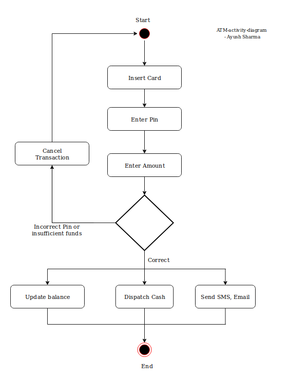
It is simply a flowchart describing the flow of control in a system. The flow can be sequential, concurrent (fork and join), or branched (decisional). It gives an idea of how the system will work when executed.
It consists of Actions and Activities. Where action is logically a single step/operation which cannot be broken down. While Activities can be decomposed into smaller activities/actions.
Eg: Modeling workflow by using activities.
ATM activity diagram example
That's all we need to know about UML. Now we are ready to pick any tool and start drawing the diagrams.
Feel free to share your feedback and the models which you are creating.
- Ayush 🙂